
Among the many components that enable modern ultrasonic technology, few are as vital and fascinating as the piezoelectric transducer. It is the core element that converts electrical signals into mechanical vibrations — the very process that allows ultrasound to perform testing, cleaning, welding, and medical diagnostics.
Understanding how these transducers work is essential for engineers seeking precision, efficiency, and reliability across various applications.
This article explains the underlying physics, construction details, materials, and industrial uses of piezoelectric transducers while highlighting emerging trends shaping the future of ultrasonics.
1. The Piezoelectric Effect
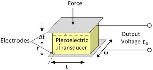
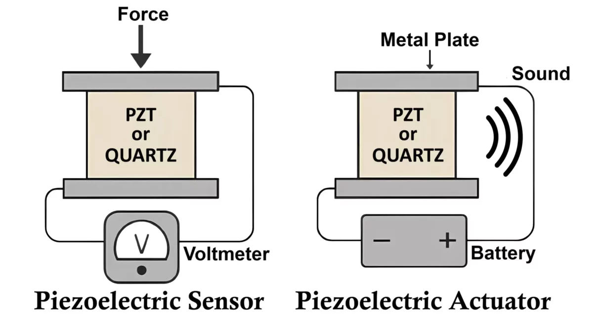
The working principle behind a piezoelectric transducer is the piezoelectric effect, a phenomenon discovered in 1880 by Pierre and Jacques Curie. Certain crystalline materials, when deformed mechanically, generate an electrical potential across their surfaces. Conversely, when an electric field is applied, these crystals undergo mechanical deformation.
This dual property — known respectively as the direct and inverse piezoelectric effects — is what enables energy conversion between electrical and mechanical domains. In ultrasonic devices, the inverse effect is utilized: an alternating current drives rapid deformation of a piezoelectric element, producing ultrasonic vibrations at frequencies typically between 20 kHz and several megahertz.
Quartz was historically used in early transducers, but modern designs predominantly rely on lead zirconate titanate (PZT) ceramics, which provide high sensitivity and a strong electromechanical coupling coefficient.
2. Construction of a Piezoelectric Transducer
A well‑designed piezoelectric transducer is a carefully tuned mechanical‑electrical system that maximizes energy conversion and minimizes loss. Its internal components typically include:
- Piezoelectric Element — the heart of the transducer. It is usually a thin disc, ring, or stack of PZT ceramic. The thickness determines its resonant frequency (half‑wavelength rule).
- Electrodes — thin metallic layers deposited on either side of the ceramic to apply an alternating voltage.
- Backing Material — an absorbing layer placed behind the element that minimizes unwanted backward reflections and broadens bandwidth.
- Matching Layer — ensures acoustic impedance matching between the transducer and the medium (usually air, water, or solid), thus improving transmission efficiency.
- Housing and Connectors — mechanical protection and an interface to electrical equipment or signal cables.
Together, these layers form a resonant system that oscillates at a predefined frequency and transmits mechanical energy effectively into the target medium.
3. Working Principle
When an alternating voltage is applied to the electrodes, the piezoelectric transducer rapidly expands and contracts along its thickness direction. If the frequency of the applied voltage matches the transducer’s resonant frequency, the vibration amplitude reaches its maximum, resulting in strong ultrasonic output.
The working process can be summarized in four stages:
- The generator supplies high‑frequency AC voltage.
- The piezoelectric crystal converts it into mechanical oscillation.
- The oscillation drives a horn, probe, or bath surface to emit ultrasonic waves.
- The waves propagate through the medium, performing inspection, bonding, or cleaning.
The efficiency of this conversion depends on the piezoelectric material constant, the geometry of the crystal, and the quality of impedance matching between electrical and acoustic circuits.
4. Types of Piezoelectric Transducers
Different ultrasonic applications require specific transducer geometries and configurations. Below are the most common types:
A. Contact Transducers
These are directly coupled to the surface using a thin film of couplant (gel, oil). Used widely in thickness measurement and manual inspection, they are simple, rugged, and maintain good signal‑to‑noise ratio.
B. Immersion Transducers
Operate through a water column that serves as a coupling medium. Favored for automated scanning and corrosion mapping, they deliver uniform coupling and enable high‑resolution imaging.
C. Angle‑Beam Transducers
Use a refractive wedge to direct ultrasonic waves into a material at a specific angle (usually 45°, 60°, or 70°). They are standard tools in weld inspection to detect incomplete fusion or cracks.
D. Dual‑Element Transducers
Contain distinct transmitting and receiving elements. One generates the pulse, and the other captures reflections, providing better near‑surface resolution.
E. Array Transducers
Comprise multiple small elements electronically controlled to steer and focus the beam. Phased array systems represent the most advanced form, enabling accurate 2D or 3D imaging.
Each type of piezoelectric transducer is optimized for certain acoustic conditions, balancing sensitivity, resolution, and penetration.
5. Materials and Their Characteristics
Material selection critically influences performance parameters such as efficiency, frequency bandwidth, and temperature stability.
Quartz (SiO₂)
- Naturally piezoelectric.
- High stability, low sensitivity.
- Used in precision timing devices more than high‑power ultrasonics.
PZT (Lead Zirconate Titanate)
- Synthetic ceramic with strong piezoelectric constants.
- High coupling efficiency and suitable for both transmission and reception.
- Drawback: contains lead — environmental limitations apply.
PVDF (Polyvinylidene Fluoride)
- Piezoelectric polymer, very flexible.
- Operating frequencies up to hundreds of MHz.
- Common in medical probes and flexible sensors.
Lead‑Free Piezo Ceramics (KNN, BNT‑BT)
- Environmentally friendly alternatives under research.
- Offer moderate coupling factors and good stability at elevated temperatures.
The exact choice depends on whether the transducer is low‑frequency (for welding/cleaning) or high‑frequency (for NDT/imaging).
6. Applications of Piezoelectric Transducers
Non‑Destructive Testing (NDT)
The most widespread use, where transducers send and receive short ultrasonic pulses through metals or composites. Reflections reveal flaws, voids, or corrosion. Advanced methods such as TOFD and phased array rely on precise transducer performance.
Ultrasonic Welding
The transducer acts as the source of vibration energy. In plastic welding, it drives a booster‑horn assembly oscillating at 20 kHz or 35 kHz to fuse materials without external heat.
Ultrasonic Cleaning
Piezo transducers mounted on a tank wall convert electrical energy into vibrational waves inside a liquid bath. The induced cavitation bubbles implode, generating micro‑jets that remove contaminants.
Medical Imaging
A transducer transmits pulses and receives echoes reflected from tissue boundaries. The resulting data builds real‑time sonograms. PVDF or composite piezoelectric materials provide excellent resolution.
Sensors and Energy Harvesters
Used for vibration detection, pressure monitoring, ultrasonic ranging, and small‑scale energy harvesting. Micro‑machined variants (MEMS) extend their use to IoT devices.
In each domain, the piezoelectric transducer remains the link between electronic control and physical action.
7. Performance Parameters and Testing
When evaluating a piezoelectric transducer, engineers focus on:
- Resonant Frequency (fᵣ): frequency of maximum output.
- Bandwidth: frequency range over which effective transmission occurs.
- Sensitivity: amplitude of received signal per unit input pressure.
- Impedance: must be matched to minimize reflections.
- Electromechanical Coupling Coefficient (k): measure of conversion efficiency.
- Capacitance: defines electrical loading characteristics.
Accurate calibration is performed using standards such as ISO 22232, EN 12668, or ASME V Article 4. Periodic testing ensures consistent performance in both industrial and laboratory environments.
8. Common Problems and Troubleshooting
Despite their reliability, piezoelectric transducers can degrade over time.
Frequent issues include:
- Cracking or Depoling: caused by mechanical impact or operation above Curie temperature.
- Delamination of Electrodes: due to moisture ingress or excessive thermal cycling.
- Impedance Drift: from connector oxidation or cable mismatch.
- Noise and Ringing: resulting from improper damping or resonant interference.
Preventive measures include controlled tightening torque, proper electrical shielding, and regular recalibration. Storage should be in a dry, temperature‑stable environment.
9. Emerging Innovations
The field of piezoelectric transducer design continues to evolve rapidly:
- Lead‑Free Ceramics: KNN and Bismuth‑based compounds are gaining traction as eco‑friendly alternatives.
- Composite Materials: Combination of PZT fibers with polymer matrices yields higher bandwidth and flexibility.
- Additive Manufacturing: 3D‑printed piezoelectric elements achieve complex geometries unattainable by traditional methods.
- Integrated Electronics: Smart transducers embed amplification and self‑diagnostic circuitry for monitoring performance in real time.
- Miniaturization (MEMS‑Scale): Enables wearable ultrasound, micro‑drones, and robotic inspection systems.
These innovations ensure the piezoelectric transducer remains at the center of ultrasonic technology 4.0 — compact, intelligent, and energy‑efficient.
10. Conclusion
The piezoelectric transducer is far more than a component; it is the bridge connecting electronics with mechanics, power with precision. From the pioneering quartz crystals of the early 20th century to today’s smart, composite ceramics, its evolution mirrors the progress of ultrasonic technology itself.
By mastering the principles of piezoelectricity, engineers unlock new possibilities in testing, welding, cleaning, sensing, and imaging — all driven by controlled vibration energy.
As research continues to refine materials and designs, ULTRASONX remains committed to pushing boundaries in custom ultrasonic transducer development, ensuring precision, performance, and sustainability for industries worldwide.